Main page
About us
Sliding Bearings Consulting
Advertising Opportunities

SubsTech’s sister website Smooth Sliding provides independent engineering consulting services that help you to solve engine bearing related issues: failures, material selection, geometry design and optimization of hydrodynamic conditions.
Smooth Sliding is an engineering consulting company run by Dr. Dmitri Kopeliovich:
- VP R&D of King Engine Bearings.
- World leading expert (32 years of experience) in design, technology and materials for Engine bearings in applications such as automotive, renewable energy, aviation, racing and others.
- Founder and owner of SubsTech (Substances & Technologies) – a leading professional website on Materials Science and Engineering.
- Author of numerous scientific and engineering publications and patents.
- Founder and owner of Smooth Sliding.
For further information and for requesting consulting services please visit our sister website Smooth Sliding.
to Metals
to Engine bearings
Failures of Engine Bearings and their Prevention
Introduction
Engine bearings are small and relatively inexpensive components of internal combustion engines however failure of an engine bearing commonly leads to serious reconditioning works of the engine including its disassembling, regrinding the crankshaft and replacing the bearings. This article describes the types of the engine bearing failures and the actions to prevent or eliminate them.
to top
Fatigue
The major type of engine bearing failure is material Fatigue. It is caused by running the bearing at load above the fatigue limit. If load acting to the bearing is higher than the fatigue strength of the material, fatigue cracks form on the bearing surface, spread towards the back layer and may result in peeling off the bearing material.
Possible causes of fatigue:
- Wrong selection of engine bearing material
- Engine power increased beyond original design
- Excessive oil clearance
- Fuel detonation/advanced ignition
- Geometry defects causing localized bearing overloading
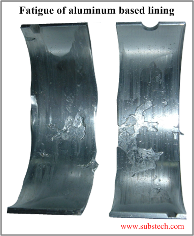
Fatigue of aluminum lining of bi-metal bearings
Fatigue of an aluminum lining appears in form of cracks, cratered and distressed bearing surface due to loss of the lining material. It may also cause extrusion of the lining material out of the bearing edges.
Fig.1 Fatigue of aluminum lining
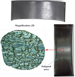
Fatigue of Babbitt overlay of tri-metal bearings
Fatigue of an overlay results in formation of irregular spider web-like cracks and craters in the overlay surface. It may lead to partial flaking of the overlay followed by fatigue of the copper base intermediate layer.
Fig.2 Fatigue of Babbitt overlay
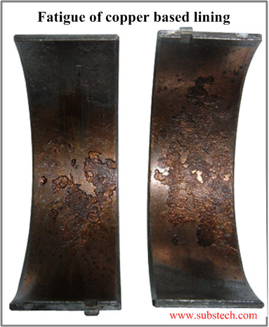
Fatigue of bronze intermediate layer of tri-metal bearings
It appears in babbitt surface missing and intermediate layer cracked and cratered. Fragments of the bronze material are detached from the steel back causing imminent bearing failure.
Fig.3 Fatigue of bronze intermediate layer
Actions to prevent/eliminate fatigue:
- Select a bearing material with higher load capacity
- Check: oil clearance and component geometry
- Retard ignition or use fuel with higher octane number
- Repair/replace distorted parts
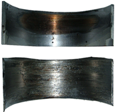
Surface wear
Wear of the bearing material is commonly a result of metal-to-metal contact between the bearing and the journal surfaces.
Surface wear may appear in the following types:
- Accelerated wear - shiny surface
- Heavy wear - signs of overheating (blackening), partial melting/removal of overlay (Fig.2, top shell)
- Severe wear - torn surface, heavy overheating, melted/missing overlay and lining material (Fig.2, bottom shell)
Fig.4 Surface wear
Possible causes of surface wear:
- Wrong selection of engine bearing material
- Engine power increased beyond original design
- Excessive oil clearance
- Fuel detonation/pre-ignition
- Geometry defects causing localized bearing overloading
Actions to prevent/eliminate wear:
- Insufficient oil supply (oil starvation)
- Non-uniform/unstable oil film (due to bearing fatigue)
- Geometrical irregularities or poor journal surface finish
- Grinding chatter marks and lobbing
- Contaminated oil
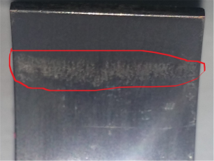
Edge wear due to distorted connecting rod
Distorted (bent or twisted) connecting rod is one of the causes of localized loading of engine bearings resulting in excessive wear of the bearing surface along the bearing edge. fatigue cracks may also form in the affected area.
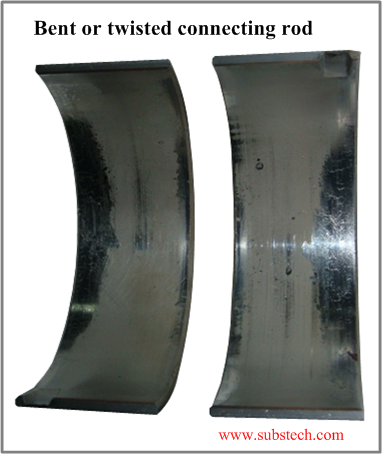 Fig.5 Edge wear due to distorted connecting rod
Possible causes of connecting rod distortion followed by edge wear:
- Overloading
- Detonation
- Excessive torque
Distorted rod produces non-parallel orientation of the bearing and journal surfaces. Metal-to-metal contact occurs along the bearing edge.
Actions to prevent/eliminate edge wear:
- Replace the distorted parts
- Prevent engine detonation and pre-ignition (check cooling system, air-fuel ratio, ignition timing, knock sensor, octane number of fuel)
- Choose higher strength connecting rods
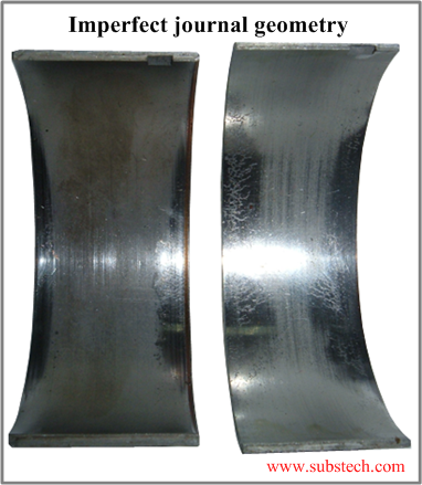
Imperfect journal geometry
Imperfect journal geometry is a cause of localized loading of engine bearings which results in wear in parts of the bearing surface. Due to local overloading fatigue cracks may occur in these areas.
Fig.6 Local wear due to imperfect journal geometry
Possible causes of local wear due to imperfect journal geometry:
- Inconsistent journal diameter. Areas of greater diameter produce metal-to-metal contact with the bearing surface, causing local wear.
- Use of worn or improperly dressed grinding wheel when resizing the crankshaft. Journals may result as tapered, hourglass shape or barrel shape.
Actions to prevent/eliminate local wear due imperfect journal geometry:
- Replace/redress grinding wheel
- Re-grind the crankshaft
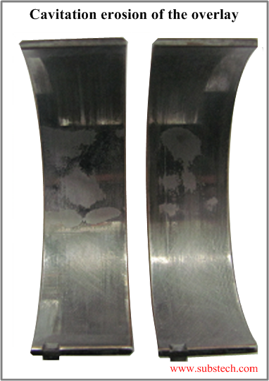
Cavitation erosion
Cavitation erosion appears in damaged areas on the overlay due to sharp changes of pressure in the oil film.
Fig.7 Cavitation erosion
Cavitation erosion of bearing material is formed by the following mechanism: Vapor cavities (bubbles) in the oil – when the load applied to a bearing fluctuates at high frequency (high RPM). The oil pressure can instantly fall, causing vapor cavities (bubbles) due to fast evaporation (boiling). When the pressure rises, vapor cavities (cavitation bubbles) contract at high velocity. Such collapse results in impact pressure, that can erode the bearing material.
Actions to prevent/eliminate cavitation erosion:
- Select stronger (harder) bearing material
- Decrease oil clearance
- Avoid running the engine at extremely high rotation speeds
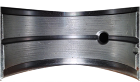
Spinning of the bearing in the housing
The indication of this failure is highly polished area on the bearing back caused by bearing spinning in the housing.
Fig.8 Spinning of the bearing in the housing
Possible causes of spinning of the bearing in the housing:
- Insufficient crush height
- Oil starvation/lugging the engine causing seizure
- Housing diameter greater than specified value
Actions to prevent/eliminate spinning of the bearing in the housing:
- Choose bearings with sufficient crush height for the application
- Eliminate the cause of seizure
- Check housing diameter for size and roundness
- Tighten bolts to the specified torque value
Fatigue in the crush relief area
This type of the bearing distress appears in form of fatigue cracks in the area of crush relief.
Fig.9 Fatigue in the crush relief area
Possible causes of fatigue in the crush relief area:
- Excessive crush height - upon torqueing the housing, the parting line region of the bearings deflects inward. This reduces the gap between the journal and bearing surfaces. Such change of bearing profile at the parting line region produces localized peak oil film pressure, which can cause fatigue of the bearing material.
- Excessive RPM producing rod bore stretch
Actions to prevent/eliminate fatigue in the crush relief area:
- Prevent excessive crush height
- Check the housing diameter
- Avoid over-torqueing the rods
- Choose more rigid connecting rods
Damage caused by foreign particles
Foreign particles circulating in oil may enter the gap between the bearing and journal and produce abrasive wear in form of circumferential scores or scratches on the bearing surface.
Fig.10 Damage caused by foreign particles
Possible causes of foreign particles presence:
- Particles of grinding abrasive entrapped in crankshaft oil passages and/or other engine block components
- Ambient dirt, sand or dust
- Metal particles (e.g. fragments of fatigued material from failed components)
Actions to prevent/eliminate abrasive wear caused by foreign particles:
- Find the origin of the abrasive particles and other contaminants
- Replace air filter, oil and oil filter
- Check crankshaft oil passages and all engine components. Thoroughly clean them with hot soapy water prior to assembly.
Related internal links
to Metals
to Engine bearings


