Main page
About us
Sliding Bearings Consulting
Advertising Opportunities

SubsTech’s sister website Smooth Sliding provides independent engineering consulting services that help you to solve engine bearing related issues: failures, material selection, geometry design and optimization of hydrodynamic conditions.
Smooth Sliding is an engineering consulting company run by Dr. Dmitri Kopeliovich:

- VP R&D of King Engine Bearings.
- World leading expert (32 years of experience) in design, technology and materials for Engine bearings in applications such as automotive, renewable energy, aviation, racing and others.
- Founder and owner of SubsTech (Substances & Technologies) – a leading professional website on Materials Science and Engineering.
- Author of numerous scientific and engineering publications and patents.
- Founder and owner of Smooth Sliding.
For further information and for requesting consulting services please visit our sister website Smooth Sliding.
to Metals
to Engine bearings
Hydrodynamic Bearing – Calculations and Design
Hydrodynamic Force
A body moving through a liquid experiences a resistance generated by the hydrodynamic force. Effect of hydrodynamic forces is principal for reliable and stable work of hydrodynamic bearings. Action of hydrodynamic force upon a subject moving in a fluid may be shown by example of a water skier (Fig.1). The force Ft pulls the skier horizontally. The gravity force Fg acts vertically and is directed downwards. Reaction of water on the moving ski produces the hydrodynamic force, which can be presented as a combination of the horizontal vector Fd (drug force) and vertical vector Fl (lift force). When the skier is skimming on the water surface, the forces are balanced: Fd counteracts Ft in the horizontal direction, whereas Fl counteracts Fg in the vertical direction.
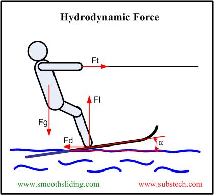
Fig.1 Hydrodynamic Force
The Fd-to-Fl ratio and their absolute values are determined by the skier speed, his weight and the wedge angle α (angle of attack). Too low towing speed and too little wedge α produce the lift force that is incapable to balance the gravity force and cause the skier to sink.
Thus for steady skiing, the three conditions are crucial:
- Sufficient speed;
- Sufficient wedge;
- Sufficient amount (depth) of the liquid (water).
Hydrodynamic Bearing
The same three conditions determine a stable work of hydrodynamic bearings. Fig.2 depicts a hydrodynamic bearing and a journal rotating in a clockwise direction. Hydrodynamic bearing is a bearing operating with hydrodynamic lubrication, in which the bearing surface is separated from the journal surface by the lubricant film generated by the journal rotation.
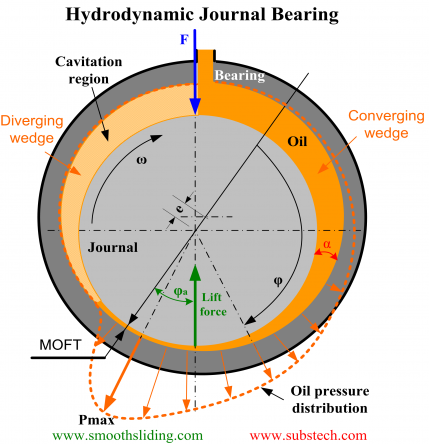
Fig.2 Hydrodynamic Bearing
Journal rotation causes pumping of the fluid flowing around the bearing in the direction of rotation.
The external force F displaces the journal from the bearing center. The journal surface is getting closer to the bearing surface forming a converging gap (wedge) α between the bearing and the journal surfaces. The presence of this oil wedge is indispensable to the normal operation of a hydrodynamic bearing.
The oil pressure creates a Lift Force separating the journal from the bearing surface. The Lift force counteracts the external force F. The lubricant enforced to squeeze through the gap between the bearing and journal surfaces produces the hydrodynamic friction.
The balance between the forces determines the final position of the journal: the value of minimum oil film thickness (MOFT) and the distance between the bearing and journal centers (eccentricity e). In the hydrodynamic regime, the journal “climbs” in the rotation direction at the angle φa (attitude angle).
to top
Reynolds Equation
A theoretical analysis of hydrodynamic lubrication was carried out by Osborne Reynolds. Lubricant pressure distribution as a function of journal speed, bearing geometry, oil clearance and lubricant viscosity is described by the Reynolds equation that is a basis for designing hydrodynamic bearings:

Where:
h – local oil film thickness,
η – dynamic viscosity of oil,
p – local oil film pressure,
U – linear velocity of journal,
x - circumferential direction,
z - longitudinal direction.
Close form solution of the Reynolds equation can not be obtained therefore finite elements method is used to solve it.
Analytical solutions of Reynolds equation exist only for certain assumptions:
- Sommerfeld Solution
The equation is solved with the assumption that there is no lubricant flow in the axial direction (infinitely long bearing assumption).
- Ocvirk Solution
Ocvirk solution for infinitely short bearing assumption neglects circumferential pressure gradients (first term of Reynolds equation).
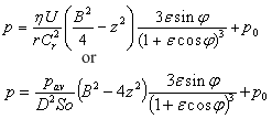
Where:
Cr – radial clearance Cr = (D-Dj)/2,
r – bearing radius,
Dj - journal diameter,
ε - eccentricity ratio ε = e/Cr,
e - absolute bearing eccentricity,
B – bearing length,
p0 - cavitation pressure,
So - Sommerfeld number So = F Ψ²/(DBωη),
F – bearing load,
Ψ – relative bearing clearance Ψ = (D-Dj)/D,
D – bearing diameter,
η – dynamic viscosity of oil,
ω – angular speed of journal.
to top
Practical Applications of Reynolds Equation
The Reynolds equation is used for calculating hydrodynamic conditions of bearing operation: minimum oil film thickness, oil temperature rise, coefficient of friction, power friction loss, oil flow rate. When a bearing is being designed, theoretical simulation of hydrodynamic lubrication is performed to optimize the bearing dimensions and lubrication conditions.
Here are three examples of application of the Reynolds Equation for optimization of hydrodynamic bearing conditions.
Example 1: Main Bearing of Internal Combustion Engine
Table 1 Input Parameters
| Bearing diameter | 68.0 mm | 2.6771” |
| Bearing length | 13.0 mm | 0.5118” |
| Rotation speed | 2000-7500 RPM | 2000-7500 RPM |
| Force | 58831 N | 13226 lbs. |
| Oil inlet temperature | 60-100 °C | 60-212 °F |
| Feed pressure | 2.0 bar | 29.0 psi |
| Diameter of lubricating hole | 3.0 mm | 0.12” |
| Angle of hole position | 0 ° | 0 ° |
| Width of oil groove | 3.0 mm | 0.12” |
| Angle of groove first end | 0 ⁰ | 0 ⁰ |
| Angle of groove second end | 180 ° | 180 ° |
| Absolute clearance | 5-150 µm | 0.2-6.0 thou |
Some of the calculation results are presented in Fig.3-6.
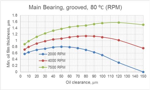
Fig.3 Effect of Oil Clearance and Rotation Speed on MOFT
The most stable hydrodynamic regime of lubrication is established at the maximum value of minimum oil film thickness (MOFT). According to the graphs in Fig.3, the optimal values of oil clearance for the bearing are as follows:
At 2000 RPM – 50 µm;
At 4000 RPM – 80 µm;
At 7500 RPM – 120 µm.
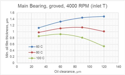
Fig.4 Effect of Oil Clearance and Oil Inlet Temperature on MOFT
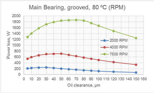
Fig.5 Effect of Oil Clearance and Rotation Speed on Power Loss
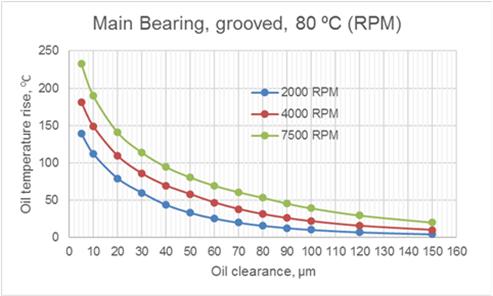
Fig.6 Effect of Oil Clearance and Rotation Speed on Oil Temperature Rise
Example 2: Bushing of Crude Oil Pump
Table 2 Input Parameters
| Bearing diameter, mm | 35.0 mm | 1.3780” |
| Bearing length | 32.0 mm | 1.2599” |
| Rotation speed | 50-500 RRM | 50-500 RRM |
| Force | 1926 N | 433 lbs. |
| Oil inlet temperature | 150 °C | 302 °F |
| Feed pressure | 0 bar | 0 psi |
| Absolute clearance | 50-100 µm | 2.0-4.0 thou |
The results of calculations are depicted in Fig.7, 8 Low rotation speeds (100-200 RPM) result in reduction of the values of minimum oil film thickness to the critical level below 0.5 µm (Fig.7).
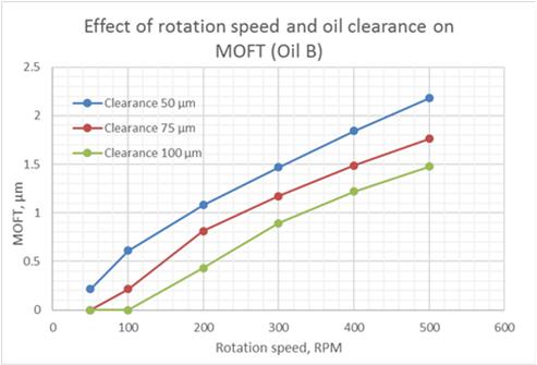
Fig.7 Effect of Rotation Speed and Oil Clearance on MOFT
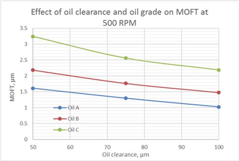
Fig.8 Effect of Oil Clearance and Oil Grade on MOFT
Example 3: Connecting Rod Bearing of Internal Combustion Engine
Table 3 Input Parameters
| Bearing diameter | 50.0 mm | 1.9685” |
| Bearing length | 20.0 mm | 0.7874” |
| Rotation speed | 1000-5000 RPM | 1000-5000 RPM |
| Force | 50000 N | 11240 lbs. |
| Oil inlet temperature | 80 °C | 176 °F |
| Feed pressure | 2.5 bar | 36 psi |
| Absolute clearance | 10-100 µm | 0.4-4.0 thou |
The calculations are made for two oil grades having different viscosity. The grade E is more viscous than the Grade D. The results of calculations are depicted in Fig.9-11.
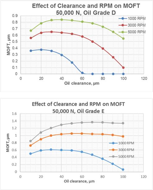
Fig.9 Effect of Rotation Speed and Oil Clearance on MOFT for Oil Grades D and E
The graphs in Fig.9 show that the oil grade E produces more stable hydrodynamic lubrication in wide ranges of the oil clearance and rotation speeds. However, the energy losses in hydrodynamic friction with the oil grade E are greater by approx. 60 % than those with the oil grade E (Fig.10).
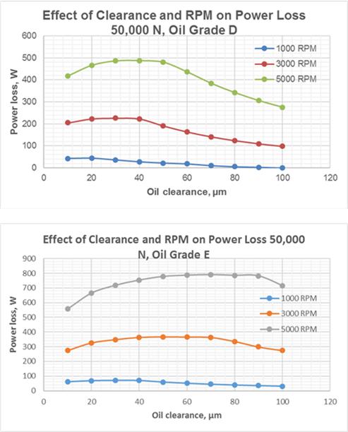
Fig.10 Effect of Rotation Speed and Oil Clearance on Power Loss for Oil Grades D and E
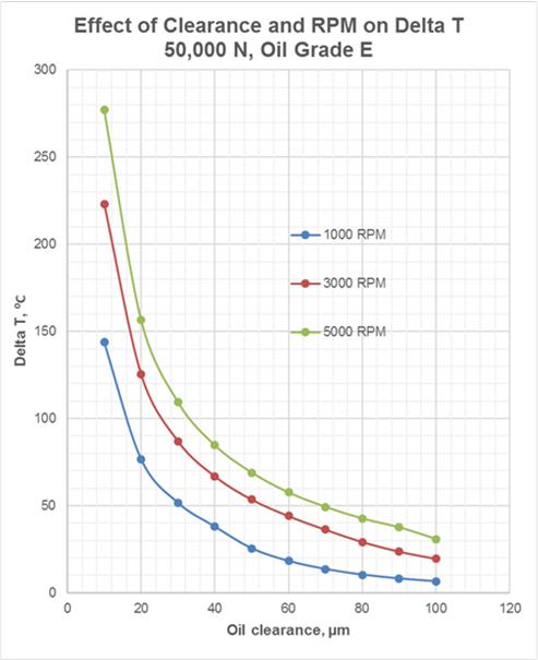
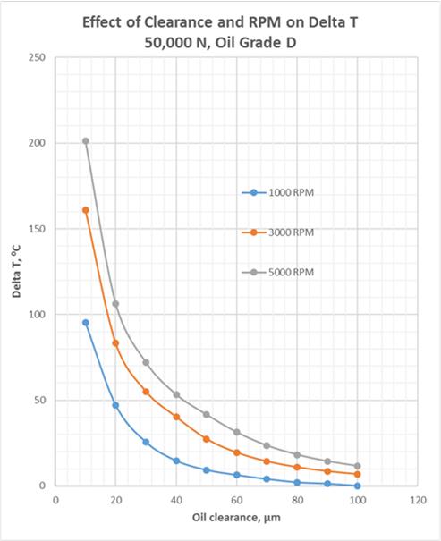
Fig.11 Effect of Rotation Speed and Oil Clearance on Oil Temperature Rise for Oil Grades D and E
Fig.12 depict the effect of the bearing loading on stability of hydrodynamic lubrication within a range of oil clearance value.
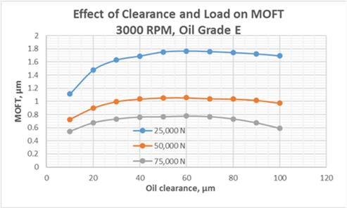
Fig.12 Effect of Oil Clearance and Bearing Load on MOFT
to top
Summary
- Basics of hydrodynamic force are explained by the example of a water skier.
- Work of hydrodynamic bearing, conditions and principal parameters of hydrodynamic lubrication are considered.
- Theoretical foundation of hydrodynamic bearing (Reynolds Equation) is described.
- Practical examples are given on application of Reynolds equation for calculating hydrodynamic conditions of bearing operation: minimum oil film thickness, oil temperature rise, power friction loss.
- It is shown, how theoretical simulations of hydrodynamic lubrication help to optimize the bearing design and lubrication conditions.
Related internal links
to Metals
to Engine bearings


